Bone offsets in Blender
Introduction
This is a short post on bone offsets rendered by Blender. While working with the CMU Motion Capture dataset, I was baffled on importing bvh files. There was a gap between the hip bone (root) and it’s children (two thighs and the abdomen). This forced me to dig deep into the inner workings of bvh files. The following resources were very helpful:
Explanation
Allow me to summarise the relevant information from the above resources:
Every joint is listed in a nested dictionary-style format, along with metadata such as the nature of MoCap data included in the bvh file and the offset of the joint from it’s parent. The length of a bone is computed using this offset. Although it might sound obvious, let me reiterate: a bone is said to connect any two joints. I like to visualise joints as point objects and bones as line segments joining any two of them. Either joint angles or joint positions (or both) are included in the bvh file. Hence, length of a bone connecting a parent joint to a child joint is determined by the offset of the child joint.
Two questions naturally pop up.
What about terminal joints?
How are their lengths inferred when they do not have a child? To tackle this, bvh files have a special End Site {.} entry which is inserted exclusively for inferring the length of the terminal bone. Refer to the code snippet below.
JOINT rIndex1
    {
      OFFSET -7.75947 0.938293 5.60832
      CHANNELS 3 Zrotation Xrotation Yrotation
      JOINT rIndex2
      {
        OFFSET -2.54057 -0.884171 1.56538
        CHANNELS 3 Zrotation Xrotation Yrotation
        End Site
        {
          OFFSET -1.62519 -0.234802 1.16502
        }
      }
    }
The OFFSET values in the End Site {.} dictionary are used to compute the length of the terminal bone which has its head at rIndex2.
What if a joint has more than one child?
This is where things get tricky. With multiple children, which child offset is used to compute the length of the bone with it’s head at the parent joint? It turns out that difference renderers use different strategies. In Blender, the offsets from each of the child bones are averaged to obtain the final offset. Consider a toy example with a hip joints as the parent with an abdomen and two thighs as the child joints.
`HIERARCHY`
JOINT hip
{
  OFFSET 0 0 0
  CHANNELS 3 Zrotation Yrotation Xrotation
  JOINT abdomen
  {
    OFFSET a b c
    CHANNELS 3 Zrotation Xrotation Yrotation
    JOINT chest
    { … }
  }
  JOINT thighL
  {
    OFFSET d e f
    CHANNELS 3 Zrotation Xrotation Yrotation
    JOINT legL
    { … }
  }
  JOINT thighR
  {
    OFFSET x y z
    CHANNELS 3 Zrotation Xrotation Yrotation
    JOINT legR
    { … }
  }
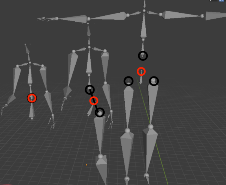
The average offset is: 1/3(a+d+x, b+e+y, c+f+z). Hence, the bone with its head at the hip joint has a tail displaced with the above offset. I tested this hypothesis by deleting each of the child joints. In the figure below, black circles denote the heads of the child bones while the red circle denotes the tail of the parent bone.
The tail of the parent (hip) bone seems to be located at the centroid of the locations of its child joints.
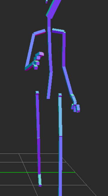
On the other hand, I discovered that an online renderer used the offset of the first child to compute the tail location. For the code snippet above, the tail of the hip bone will be located at [a, b, c] since the chest bone is listed before the thigh bones.
The same bvh file (used in the previous figure) is rendered online. Observe that the hip joint is connected to the abdomen since abdomen happens to be the first child in the hierarchy.
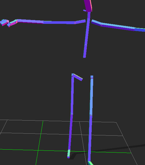
If I switch the order of the child joints (right thigh before abdomen), notice how the tail of the hip bone changes accordingly.
Hope this post helped clear any confusion.
Feel free to contact me if you find any errors in the post. Would be glad to connect!